Hole Design Although the split seam. This gives improved protection to higher power jet penetration.
How To Ensure Bolted Joint Integrity When Using A Compression Limiter In A Plastic Assembly Fluid Power Journal
Compression limiters are non-threaded bushings that strengthen the plastic and resist the applied compressive loads.
. It provides bolt clearance while the wall of the compression limiter withstands the compressive force induced during the assembly of the mating screw or bolt. 2 Tappex 2019 Brochure. 1 Prepare holes with a taper of 1.
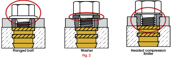
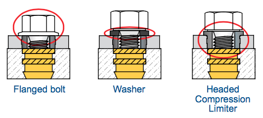
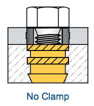
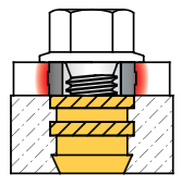
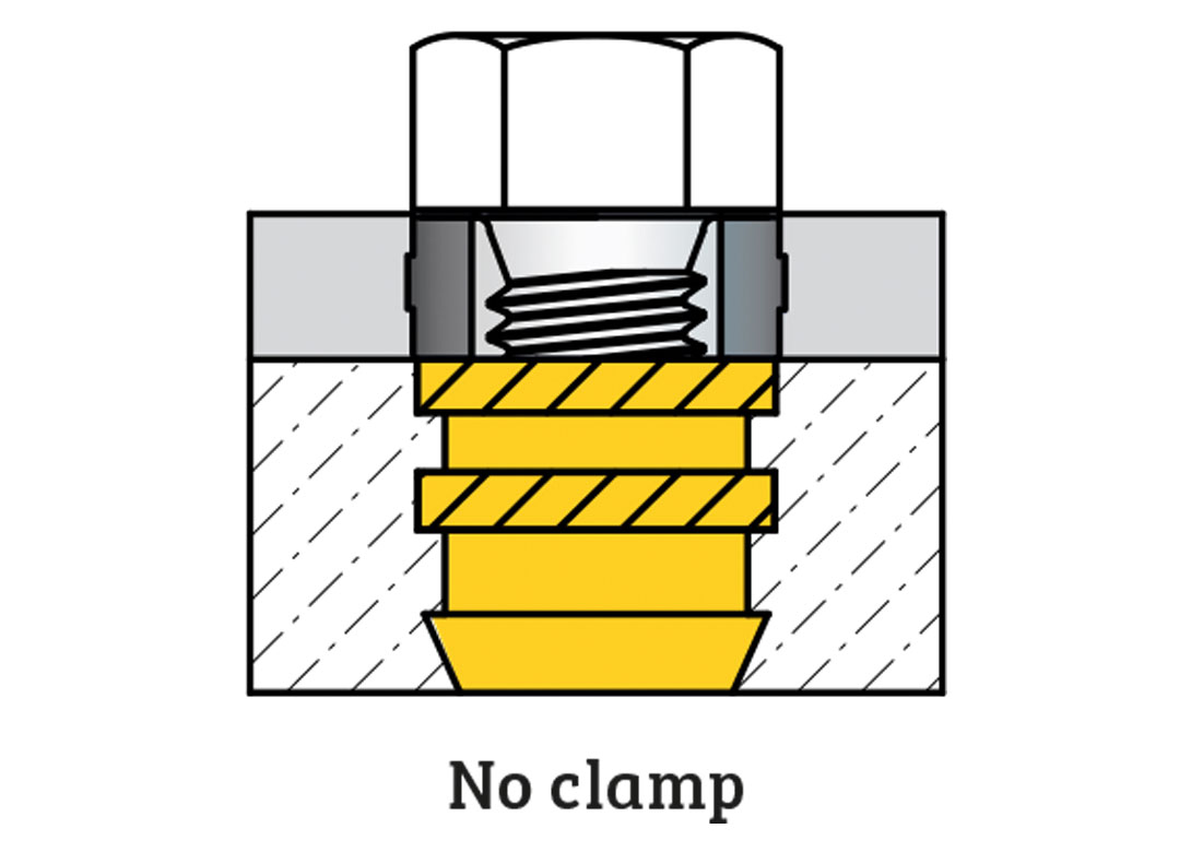
The prevent compression of the plastic part under the forces of the tightened screw. Standard joint Allows joint face contact. The following design guidelines should be considered when a Compression Limiter is used to ensure its effectiveness in the plastic assembly.
The Compression Limiters length should be designed to ensure it will bottom out against the surface under the bolts head and mating component. SI Brand Compression Limiters. Guidance and advice for those involved in the design of plastic products requiring threaded inserts.
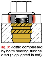
The integrity of the plastic is not compromised by the load that is applied. The primary function of a Compression Limiter is to provide and. Compression Limiters are plain hole metal inserts designed for use in plastic mould components.
Dodge Applications Engineers are available and ready to assist you in the design and development of the optimum bushing for. The appropriate length and length tolerance is application dependent. The compression limiter strengthens the plastic and withstands the compressive force that is applied when a mating screw is tightened.
Headed Compression Limiters are only available as solid components because of the tolerances required for proper Compression Limiter operation. Compression Limiters are plain hole metal inserts designed for use in plastic mould components. To function properly bearing surface beneath the bolts head must extend over the Compression Limiter to contact the plastic component.
Below or download the Compression Limiters Design Guide. 1 Design Guide Threaded Inserts For Plastics a ten point guide. A physical compression limiter is required.
They are designed with various knurl configurations and undercuts in order to meet the strength requirements of the specific application. Danielson CT SPIROL recently released their new Compression Limiter Design Guide that provides essential design guidelines for the ideal bolted joint in plastic assemblies. Design guidelines for Compression Limiters to avoid the risk of exceeding the elastic limit of the plastic component.
This Design Guide has been put together to assist designers working in any industry on how best to incorporate a foam seal into their design. SPIROL recently released their new Compression Limiter Design Guide that provides essential design guidelines for the ideal bolted joint in plastic assemblies. Included are the specifications for their standard split seam molded-in and solid wall designs as well as their brand new oval series.
SPIROL recently released their new Compression Limiter Design Guide that provides essential design guidelines for the ideal bolted joint in plastic assemblies. Compression Limiters are plain hole metal inserts designed for use in plastic mould components. Included are the specifications for their standard split seam molded-in and solid wall designs as.
Below or download the Compression Limiters Design Guide. Compression Limiters Dodge non-threaded bushings expand the Dodge offering and are custom designed for your specific application. They are designed to minimize any.
Compression Limiters are used to protect plastic components in bolted joints and maintain a threaded fasteners clamp load by eliminating plastic creep. For technical drawings and 3-D models click on a part number. The Compression Limiters length should be designed to ensure it will bottom out against the surface under the bolts head and mating component.
Anti-Creep Spacers Compression Limiters. Hole Design Although the split seam Compression Limiters have a broken edge. 2 The plastic walls must have a thickness that is at least 50 of the diameter of the screw to.
COMPRESSION LIMITERS may be pressed in or installed by heat staking or ultrasonic welding. Tubular Compression Limiters may be inserted molded directly into an assembly or may be pressed in after molding. Bolt head applies a clamp load on the plastic and bottoms out on the Limiter.
Included are the specifications for their standard split seam molded-in and solid wall designs as. The clearance between the bolt and the inside diameter of the installed Compression Limiter is adequate to meet normal misalignment. Compression limiters are non-threaded inserts that are commonly used in applications where a compressive load is applied to a plastic assembly.
Made from brass these inserts are nonmagnetic mildly corrosion resistant and electrically conductive. Compression Limiters are metal inserts designed to protect molded plastic components from the compressive loads generated by the tightening of bolts or screws. Commonly compression limiters are installed using a simple cold press assembly method.
The Limiters can be pressed in or installed with either heat or ultrasonics. Solid compression limiters provide a strong and reliable defence against the stresses caused by fastener torque. Installation of Compression Limiters can be done through various technique using heat.
Also known as compression limiters they keep screws securely installed even if the surrounding plastic expands or shrinks when the screw is tightened. It is recommended that the toleranced 2D drawing of the part be used for. The appropriate length and length tolerance is application dependent.
Design guidelines for Compression Limiters to avoid the risk of exceeding the elastic limit of the plastic component. Compression limiters are non-threaded bushings made of various materials. The clearance between the bolt and the inside diameter of the installed Compression Limiter is adequate to meet normal misalignment.
Design guidelines for Compression Limiters to avoid the risk of exceeding the elastic limit of the plastic component. Bolt is tightened to 75 of its proof load.
How To Ensure Bolted Joint Integrity When Using A Compression Limiter In A Plastic Assembly Medical Design And Outsourcing
How To Ensure Bolted Joint Integrity When Using A Compression Limiter In A Plastic Assembly Fluid Power Journal
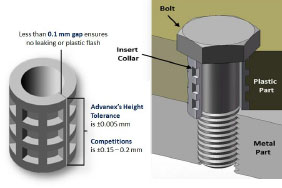
Advanex Europe Insert Collar Compression Limiters
How To Ensure Bolted Joint Integrity When Using A Compression Limiter In A Plastic Assembly Medical Design And Outsourcing
2
How To Ensure Bolted Joint Integrity When Using A Compression Limiter In A Plastic Assembly Medical Design And Outsourcing
How To Ensure Bolted Joint Integrity When Using A Compression Limiter In A Plastic Assembly Fastener Fixing Magazine

How To Ensure Bolted Joint Integrity When Using A Compression Limiter In A Plastic Assembly Fastener Fixing Magazine
0 comments
Post a Comment